Tampilkan postingan dengan label sharp. Tampilkan semua postingan
tv sharp alexander protek

tv sharp alexander protek

Proteksi pada televisi Sharp berfungsi untuk melindungi rangkaian dari kerusakan yang lebih serius ketika terjadi gangguan pada bagian tertentu. Pada chassis GA-4M, sistem proteksi dapat dipicu oleh tegangan B+, ABL/X-Ray, heater, tuner, maupun regulator. Berikut beberapa titik proteksi yang dapat diperiksa saat melakukan proses trouble shooting.

Televisi Sharp Alexander Slim II 21 inci chassis GA-4M sebagai referensi letak jalur proteksi.
Sharp Alexander Slim II 21 inci chassis GA-4M yang menggunakan IC IXB226WJ/IXB722WJ dan M61260.

Sharp Alexander Slim II 21 Inci
Chassis GA-4M, IC IXB226WJ / IXB722WJ, M61260.

  • Nonaktifkan proteksi utama pada Pin 7 IC1001 (4,5 Volt).
  • D605 – Tegangan 185V, Anoda D605 = 4,5 Volt → Lepaskan D605.
  • D608 – Jalur ABL / X-Ray, Katoda D608 = 4,5 Volt → Lepaskan D608.
  • Q603 – Jalur Heater, Collector Q603 = 4,5 Volt → Lepaskan Q603.
  • D203 – Tegangan 33V (Tuner), Anoda D203 = 4,5 Volt → Lepaskan D203.
  • D1091 – Tegangan 9V, Anoda D1091 = 4,5 Volt → Lepaskan D1091.
  • Pin 6 IC1001 (3,4 Volt) – D1010 Tegangan 15V, Pin 6 IC1001 = 3,4 Volt → Lepaskan D1010.

Kesimpulan

Sistem proteksi pada TV Sharp Alexander Slim II chassis GA-4M dirancang untuk mencegah kerusakan yang lebih serius saat terjadi gangguan pada rangkaian. Dengan memeriksa titik proteksi seperti D605, D608, Q603, D203, D1091, D1010, serta tegangan pada IC1001, proses troubleshooting dapat dilakukan secara lebih cepat dan terarah. Pastikan setiap pengukuran dilakukan dengan hati-hati serta aktifkan kembali rangkaian proteksi setelah proses perbaikan selesai agar televisi tetap bekerja dengan aman dan normal.

Baca Selengkapnya: tv sharp alexander protek
Sharp Wonder Gambar Gelap

Sharp Wonder Gambar Gelap

Sharp Wonder Gambar Gelap
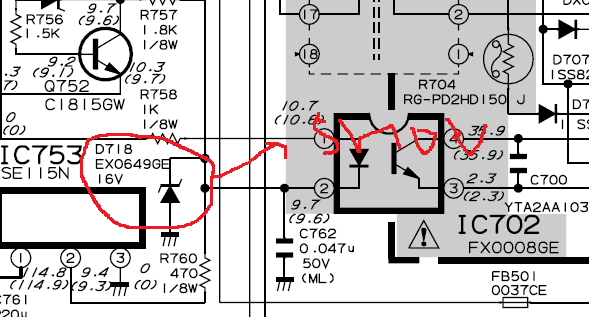
Sempat beberapa hari ini dibuat pusing kerusakan sharp wonder yang kata empunya tv sebelum mati sempet bunyi pletak pletak didalam box tv .setelah saya cek ketempat yang punya tv memang benar tv sudah mati lampu led ga nyala pikirku tv sharp mati total cek sana sini ternyata ic mati normal hanya stanby cek tegangan stanby 3,3volt tanpa beban normal kasih beban turun dratis Tegangan suply tegangan Drop cek sana sini ketemu biang keroknya D718 ato Dioda zener 16volt lokasi deket Photocoupler setelah tak ganti jreng... tv stanby lampu hidup warna merah tak pencet chanel hidup lampu kuning nyala apa yang terjadi pletak bell.... keluar asap pada flyback.... cek flyback di luar mulus   eh... flybacknya tak copot ternyata benar di bagian bawah hangus .... penyakit lagi hih... gumamku setelah tak ganti yang baru tak coba tv hidup hore...... ga ada gambar OSD keluar suara normal tak coba scen tak naikin malah gari zig zag . tak cek ABL masya alloh tegangan 0volt.... TERNYATA BIANG KEROKNYA R604 1/8 wat 39kilo putus tidah hanya sampai di situ Capasitor C602 100n shot cek lagi R609 hangus kebetulan ada pasien sama beda kerusakan tak cocokin R609 ukuranya 22kilo ohm dan setelah tak ganti semua saatnya yang mendebarkan tak coba owalah sama saja to.... gambar gelap nantang nih tv ... cek lagi Rgbnya tegangan drop alias kecil sekali alias ga normal kali ya....tak urut jalurnya R807 putus hayo R ukuranya berapa?.... buka kitab kitab skema tv sharp R 10k. setelah pergantian langsung tak coba lagi wiihhhhh...... akhirnya tv belum juga bergeming layar masih gelap tanpa pikir panjang menuju bagian vertikal tak obrak abrik tanpa ampun ketemu lagi D512 dalam keadaan bocor terukur bolak balik di avo meter ku cuman satu strip bocor ganti lagi MEN.... tak coba lagi tak colokin akhirnya usaha yang tidak sia sia raster pun muncul tak tutup tak coba 1 jam tv masih normal....
oke buat temen temen service barang kali  bermanfaat dan met menjalankan ibadah puasa
Baca Selengkapnya: Sharp Wonder Gambar Gelap
Menu Service LCD tv Sharp

Menu Service LCD tv Sharp

Sharp LCD TV No Power and the Power LED is flashing.
EXAMPLE CASE Below
Number: LCD TV-269 Model(s): LC52E77UN(A)
LCD Television Sharp Electronics Corporation
Services and Solutions
Subject: No Power and Power LED is flashing 1X
Symptom: TV will not turn on and front indicator LEDs are flashing. TV may in some cases come on
and exhibit flashing backlights. Most commonly occurs when the TV is used for the very first time.
Cause: One or both of the Inverter Units is not fully seated.
(RUNTKA528WJN1 TOP / RUNTKA529WJN1 BOTTOM)
Solution: Properly seat the Inverter Unit (s) fully into a locked position.
Steps to Repair:
Refer to disassembly procedure for Rear Cabinet as described in Service Manual
Examine both Inverter Units to see if they are improperly installed.
If either or both Inverter Units are not properly seated please apply minimal force onto PWB, nearest the
clips, to lock it into place.
Steps to Reset:
Hold in ............................... buttons on the TV
Continue to hold in the buttons and plug in the TV
TV will turn on by itself and a small “K” will now be present on the screen in the upper left
Release both buttons
Simultaneously press ................................... one time on the TV
Service Menu should now be showing
If “LAMP ERROR” shows other than a Zero please reset it (Refer to Service Menu Detailed Instructions)
If Monitor Error Cause is other than ZERO please reset it (Refer to Service Menu Detailed Instructions)
Perform Industry Init (Refer to Service Menu Detailed Instructions)
Unplug the TV upon completion of Industry Init (green screen)
Wait 30 seconds and plug in TV
Steps to Test:
15) Check the TV for functionality and POWER ON / OFF several times
16) Unplug the TV after testing is successful
17) Repeat steps 4 thru 9 to ensure that no errors are present
Service Menu Detailed Instructions
Lamp Error Reset
Service Menu screen should be showing on the screen
Using the remote control, press the Down Select .......... button one time (button is ........)
The upper left corner of the service menu screen should indicate “2/41”
Use the ................ button on the remote to highlight the line “LAMP ERROR RESET OFF”
Use the Volume Up button on the remote to change the “OFF” to “ON” and press ENTER button
The error is now reset
Monitor Error Cause Reset
Service Menu screen should be showing on the screen
Using the remote control, press the .......... button five times (button is ..........)
The upper left corner of the service menu screen should indicate “........”
Use the Channel Down button on the remote to highlight the line “MONITOR ERROR CAUSE RESET OFF”
Use the Volume Up button on the remote to change the “OFF” to “ON” and press ENTER button
The error is now reset
Industry Init
Service Menu screen should be showing on the screen
Using the remote control, press the Down Select Arrow button one time (button is under ENTER)
The upper left corner of the service menu screen should indicate “2/41”
Use the Channel Down button on the remote to highlight the line “INDUSTRY INIT OFF”
Use the Volume Up button on the remote to change the “OFF” to “ON” and press ENTER button
The line “INDUSTRY INIT ON” will change to “//////////////” briefly
When Industry Init is complete the screen will be green
Baca Selengkapnya: Menu Service LCD tv Sharp
Sharp universe 20U250 MATI TOTAL

Sharp universe 20U250 MATI TOTAL

Barusan tadi benerin tv sharp universe ic tda9381ps dalam keadaan mati total kata yang punya tv kemarin hujan lebat di sertai petir yang menggelegar sampai menurunkan mcb pln setelah hujan reda berikut petirnya tv nya di nyalain ternyata bunyi pletak ga nyala katanya kena petir ,,, langsung dah ambillangkah seribu tv tak bongkar dalam hati pasti akan terjadi perang  besar kucari gejala kerusakan fisik spt komponen terbakar dll,aman aman saja.kuteliti solderan retak di sekitar daerah regulator primer,sekunder,horizontal dan vertikal,semuanya juga aman.Setelah kuukur tegangan output dari trafo gak keluar sama sekali tak cek regulator yang biasanya  Zener 5,6volt matot tapi normal cek D705 dalam keadaan shot D705
D705 DAN D705 SHOT


 juga shot sampai pengecekan photocoupler di urut ketemu lagi juga shot

D718 SHOT

 juga STR 6654 JUGA SHOT PADA Pin no.1 dan pin no5 setelah tak ganti smua berikut photocouplernya danjuga C 719 4.7UF 160VOLT tak tak lupa kabel defleksi youke di copot berikut b+ flyback untuk menghindari lonjakan B+ nyalain jreng lampu led jadi merah akhirnya tak pasang lagi kabel defleksi tak nyalain makbyak.,.. protek brooo.,.,. led hijau hanya nyala sebentar tak coba masuk service buka j 223 byak tv nyala tak ukur ukur tegangan normal smua iseng2 tak pasang lagi j 223 colok lagi jecknya byarrrrrr,,,, langsung tv normal tak tutup di tes selama 1jam tetep normal suksess... !!!

Bagi sobat yang mau donlod skema  TVSHARP-WONDER_UNIVERSE_TDA9381PS  klik disini


Baca Selengkapnya: Sharp universe 20U250 MATI TOTAL
Sharp chasis UA-1 Raster gelap

Sharp chasis UA-1 Raster gelap


Sharp chasis UA-1 Raster gelapMenurut pengalaman kami sebagai tukang sampah Service TV hal dapat disebabkan karena bermacam-macam problem. Setiap model TV SHARP belum tentu sama penyebabnya. Dibawah ini adalah catatan kami tentang problem-problem yang kemungkinan dapat menyebabkan raster blank
 Raster gelap masuk service mode ok,
 keluar service mode gelap lagi.
Penyebab : data eprom berubah.
Solusi : ubah data service mode EVG dari 1 ke 0 dan EHT dari 1 ke 0
Catatan : model chasis UA-1 universe & wonder
SELAMAT MENCOBA SEMOGA BERHASIL
Baca Selengkapnya: Sharp chasis UA-1 Raster gelap
Sharp piccolo gambar mengecil bagian atas dan bawah

Sharp piccolo gambar mengecil bagian atas dan bawah


Sharp piccolo gambar mengecil bagian atas dan bawah
Penyebab : resistor antara playback yg menuju ic vertikal putus
Solusi : ganti dengan nilai yg sama,apa bila tidak ada perubahan ganti ic vertikal dengan yg baru Catatan : cek juga elco yg ada pada bagian vertikal kemungkinan ada yg lemah
Semoga membantu Sob
Baca Selengkapnya: Sharp piccolo gambar mengecil bagian atas dan bawah
Pin Protect tv sharp

Pin Protect tv sharp

Sharp

Chasis UA-1, Menggunakan IC IX3368CEN1-5 Atau IX3410CEN1-5
Masukan Proteksi
Detektor
Yang Dideteksi
Tegangan Normal
Menonaktifkan Proteksi
Pin No.8 IC801 (3,3 V)
Menonaktifkan Proteksi utama,

Lepaskan Jumper J223
D609
Tegangan 8V
Anoda D609 = 3.3 Volt
Lepaskan D609
D606
ABL / X-ray
Anoda D606 = 3.3 Volt
Lepaskan D606
D614, Q603
Heater / X-ray
Anoda D614 = 3.3 Volt

Collector Q603 = 3.3 Volt
Lepaskan D614

Lepaskan Q603
D752
Tegangan 5V
Anoda D752 = 3.3 Volt
Lepaskan D752
D504
Tegangan 16V (Sound Amp)
Anoda D504 = 3.3 Volt
Lepaskan D504
D502
Tegangan 45V (Vertikal)
Anoda D502 = 3.3 Volt
Lepaskan D502
D503
Vertikal Output
Anoda D503 = 3.3 Volt
Lepaskan D503
D613
Tegangan 180V
Anoda D613 = 3.3 Volt
Lepaskan D613
Chasis UA-1 (Lubang), Menggunakan IC IX3368CEN7
Masukan Proteksi
Detektor
Yang Dideteksi
Tegangan Normal
Menonaktifkan Proteksi
Pin No.8 IC801 (3,4 V)
Menonaktifkan Proteksi utama,

Lepaskan Jumper J208 dan D203
D203
Tegangan 33V (Tuner)
Anoda D203 = 3.4 Volt
Lepaskan D203
D607
Tegangan 190V
Anoda D607 = 3.4 Volt
Lepaskan D607
D604, Q603
Heater / X-ray
Anoda D604 = 3.4 Volt

Collector Q603 = 3.4 Volt
Lepaskan D604

Lepaskan Q603
D601
ABL / X-ray
Anoda D601 = 3.4 Volt
Lepaskan D601
Q501
Tegangan Supply Vertikal
Collector Q501 = 3.4 Volt
Lepaskan D501
Menggunakan IC IX 2938CE, TB1226
Masukan Proteksi
Detektor
Yang Dideteksi
Tegangan Normal
Menonaktifkan Proteksi
Pin No.30 IC1001 (5,1 V)
D616
Tegangan 9V
Anoda D616 = 5.1 Volt
Lepaskan D616
D607
Tegangan 180V
Anoda D607 = 5.1 Volt
Lepaskan D607
Q607
Heater / X-ray
Collector Q607 = 5.1 Volt
Lepaskan Q607
D606
ABL / X-ray
Anoda D606 = 5.1 Volt
Lepaskan D606
D611
Tegangan 5V
Anoda D611 = 5.1 Volt
Lepaskan D611
D201
Tegangan 9V
Anoda D201 = 5.1 Volt
Lepaskan D201
Menggunakan IC IX 2694, M52340
Masukan Proteksi
Detektor
Yang Dideteksi
Tegangan Normal
Menonaktifkan Proteksi
Pin No.38 IC1001 (0 V)
D606
Heater / X-ray
Anoda D606 = 0 Volt
Lepaskan D606
D616
ABL / X-ray
Anoda D616 = 0 Volt
Lepaskan D616
Q603
ABL / X-ray
Collector Q603 = 0 Volt
Lepaskan Q603
D610
Heater / X-ray
Anoda D610 = 0 Volt
Lepaskan D610
Chasis G2 Menggunakan IC IX 3031CE, TB1226
Masukan Proteksi
Detektor
Yang Dideteksi
Tegangan Normal
Menonaktifkan Proteksi
Pin No.30 IC1001 (3,3 V)
D618
Tegangan 9V
Anoda D618 = 3,3 Volt
Lepaskan D618
D607
Heater / X-ray
Anoda D607 = 3,3 Volt
Lepaskan D607
Q607
Heater / X-ray
Collector Q607 = 3,3 Volt
Lepaskan Q607
D606
ABL / X-ray
Anoda D606 = 3,3 Volt
Lepaskan D606
D611
Tegangan 5V
Anoda D611 = 3,3 Volt
Lepaskan D611
GA-4M Chasis, Menggunakan IC IXB226WJ, M61260
Masukan Proteksi
Detektor
Yang Dideteksi
Tegangan Normal
Menonaktifkan Proteksi
Pin No.7 IC1001 (4.5 V)
D605
Tegangan 185V
Anoda D605 = 4,5 Volt
Lepaskan D605
D608
ABL / X-ray
Katoda D607 = 4,5 Volt
Lepaskan D608
Q603
Heater
Collector Q603 = 4,5 Volt
Lepaskan Q603
D203
Tegangan 33V (Tuner)
Anoda D203 = 4,5 Volt
Lepaskan D203
D1091
Tegangan 9V
Anoda D606 = 4,5 Volt
Lepaskan D1091
Pin No.6 IC1001 (3.4 V)
D1010
Tegangan 15V
Pin No.6 IC1001 = 3.4 Volt
Lepaskan D1010
Chasis GA-6, Menggunakan IC IXB725WJ, Chasis GA-7 Menggunakan IC IXB855WJZZ
Masukan Proteksi
Detektor
Yang Dideteksi
Tegangan Normal
Menonaktifkan Proteksi
Pin No.63 IC801 (4.1 V)
D1005
Tegangan 9V
Anoda D1005 = 4,1 Volt
Lepaskan D1005
D608
ABL / X-ray
Katoda D608 = 4,1 Volt
Lepaskan D608
Q603
Heater
Collector Q603 = 4,1 Volt
Lepaskan Q603
D805, D203
Tegangan 33V (Tuner)
Anoda D805 & D203 = 4,1 Volt
Lepaskan D203
D204
Tegangan 5V (Tuner)
Anoda D204 = 4,1 Volt
Lepaskan D204
Pin No.7 IC801 (3.9 V)
D1002
Power supply (AC-Detect)
Pin No.7 IC801 = 3.9 Volt
Lepaskan D1002
Pin No.8 IC801 (0.6 V)
R523
Vertical
Pin No.8 IC801 = 0.6 Volt
Lepaskan R523
Menggunakan IC IXC080WJN5Q
Masukan Proteksi
Detektor
Yang Dideteksi
Tegangan Normal
Menonaktifkan Proteksi
Pin No.63 IC801 (4.1 V)
Menonaktifkan Proteksi utama,

Lepaskan Jumper J497
D1108
Tegangan 5V
Anoda D1008 = 4,1 Volt
Lepaskan D1108
D605
Tegangan 185V
Katoda D605 = 4,1 Volt
Lepaskan D605
D608, D607
ABL / X-ray
Katoda D608 = 4,1 Volt
Lepaskan D608
Q603, D604
Heater / X-ray
Collector Q603 = 4,1 Volt
Lepaskan Q603
D203
Tegangan 33V (Tuner)
Anoda D203 = 4,1 Volt
Lepaskan D203
D1105
Tegangan 5V
Anoda D1105 = 4,1 Volt
Lepaskan D1105
Pin No.64 IC801 (3.9 V)
D1002
Power supply (AC-Detect)
Pin No.64 IC801 = 3.9 Volt
Lepaskan D1002
Pin No.65 IC801 (0.6 V)
R523
Vertical
Pin No.65 IC801 = 0.6 Volt
Lepaskan R523
Menggunakan IC IXC688WJ / IC IXC844WJ
Masukan Proteksi
Detektor
Yang Dideteksi
Tegangan Normal
Menonaktifkan Proteksi
Pin No.81 IC801 (4.1 V)
D1108
Tegangan 5V
Anoda D1008 = 4,1 Volt
Lepaskan D1108
D605
Tegangan 185V
Katoda D605 = 4,1 Volt
Lepaskan D605
D608, D607
ABL / X-ray
Katoda D608 = 4,1 Volt
Lepaskan D608
Q603, D604
Heater / X-ray
Collector Q603 = 4,1 Volt
Lepaskan Q603
D203
Tegangan 33V (Tuner)
Anoda D203 = 4,1 Volt
Lepaskan D203
D1105
Tegangan 5V
Anoda D1105 = 4,1 Volt
Lepaskan D1105
Pin No.82 IC801 (3.9 V)
D1002
Power supply (AC-Detect)
Pin No.82 IC801 = 3.9 Volt
Lepaskan D1002
Pin No.83 IC801 (0.6 V)
R523
Vertical
Pin No.83 IC801 = 0.6 Volt
Lepaskan R523
Baca Selengkapnya: Pin Protect tv sharp